
Wall thickness is one of the easiest numbers to compare in a street light pole quotation, but it is also one of the easiest to misunderstand. A thicker pole is not automatically a better pole, and the same thickness should not be copied from one project to another. Pole height, taper, outside diameter, steel grade, luminaire weight, arm projection, wind exposure, access-door size, mounted equipment and service environment all affect the final structural requirement.
For buyers and project contractors, the practical question is not simply “How many millimeters should the pole be?” The better question is: what pole section can safely carry the required loads throughout the intended service life? Wall thickness is one part of that answer.
1. Start With the Complete Pole Geometry, Not Thickness Alone
A street light pole behaves like a cantilever structure. Wind pressure acting on the pole, luminaire and arm creates bending moment that becomes greatest near the base. Wall thickness therefore has to be evaluated together with bottom diameter, top diameter, taper, pole height and steel strength.
Two 8 m poles can both use 3.5 mm steel and still have different capacities if one has a larger bottom diameter or a higher-strength steel grade. Likewise, increasing thickness without checking the flange, anchor bolts and weld details does not create a balanced design. For preliminary selection, ask for the complete pole drawing rather than only a height-and-thickness specification.
2. Use Pole Height as the First Screening Factor
Height is a practical starting point because taller poles normally experience greater bending forces and wind exposure. For common tapered galvanized steel street light poles, the following values can be used as an initial reference before structural verification:
| Pole Height | Typical Starting Wall Thickness | Common Application |
| 5-7 m | about 3.0 mm | Residential roads, community streets, small parking areas |
| 8 m | about 3.5 mm | Urban streets and general road lighting |
| 9 m | about 3.75 mm | Wider roads and higher-output luminaires |
| 10 m | about 4.0 mm | Main roads, long arms or heavier luminaires |
| 12 m | about 4.5 mm | Wide roads, higher mounting positions and larger loads |
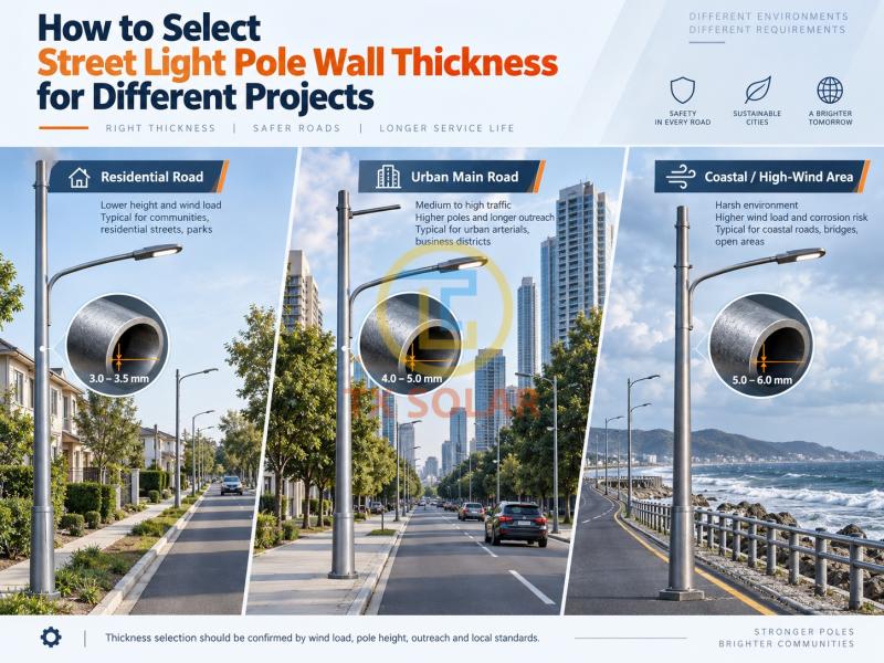
These figures are not universal design rules. A project may require a thicker wall, a larger pole diameter, a stronger steel grade, or a combination of all three. Final dimensions should be confirmed from design wind speed, terrain category, equipment load and applicable local structural requirements.
3. Increase Structural Capacity for High-Wind or Exposed Sites
Wind is often the factor that turns a standard pole into a customized pole. Coastal roads, open highways, bridges, ports, desert areas and elevated locations can have much higher exposure than sheltered urban streets.
When wind requirements rise, increasing wall thickness is only one possible response. Engineers may also enlarge the bottom diameter, adjust the taper, use higher-strength steel, strengthen the flange and anchor system, or reduce the projected area of the arm and equipment. Buyers should provide the required design wind speed and installation environment at the quotation stage; “strong wind area” is too vague for accurate structural selection.
4. Check Arm Length and All Equipment Mounted on the Pole
A pole carrying a short single-arm LED street light is different from a pole supporting long double arms, solar panels, battery boxes, cameras, signs or smart-city devices. Extra weight increases gravity load, while a larger projected surface increases wind load.
Long arms are especially important because they place the luminaire farther from the pole centerline and increase bending. For solar street lights, do not select wall thickness from lamp wattage alone. The panel dimensions, installation angle and mounting position can have a major effect on wind loading.
5. Pay Attention to the Access Door and Local Reinforcement
The access door is one of the most critical local details on a street light pole. Cutting an opening near the lower section removes steel from an area where bending stress is high. A large or poorly positioned door can reduce local stiffness even when the nominal wall thickness looks sufficient on paper.
The pole design should therefore define the door size, orientation, reinforcement plate or frame, weld quality and distance from the flange. Smart poles and poles with larger electrical compartments need particular attention because their openings are usually larger than those of standard street light poles.
6. Separate Corrosion Protection From Structural Thickness
Hot-dip galvanizing protects the steel surface, but galvanizing thickness should not be confused with steel wall thickness. The zinc coating improves corrosion resistance; it does not replace the structural steel required to resist wind and equipment loads.
Projects near the sea, in industrial zones or in persistently wet environments may need a more demanding corrosion-protection specification. Buyers should define the structural wall thickness and the surface-protection requirement separately so that neither item is overlooked.
7. Avoid Choosing the Thickest Pole by Default
Over-specifying thickness increases steel consumption, transport weight and project cost without necessarily solving the actual design problem. A heavier pole can also demand a larger foundation and more difficult lifting during installation.
A good pole design uses material where it contributes most to strength and stiffness. The goal is not maximum thickness; it is sufficient structural capacity with a coordinated pole body, flange, anchor bolts, arm and foundation. This matters especially on large projects where a small unnecessary increase in steel per pole can become a significant total cost.
8. Information to Confirm Before Ordering
Before a street light pole manufacturer finalizes wall thickness, the buyer should provide or confirm the following information:
• pole height and required top/bottom diameters;
• single arm, double arm or special bracket configuration;
• arm length, luminaire weight and projected area;
• solar panel, camera, sign or other equipment dimensions and weights;
• project design wind speed and installation terrain;
• steel grade and minimum mechanical requirements;
• access-door dimensions and reinforcement details;
• flange size, anchor bolt arrangement and foundation interface;
• galvanizing or coating requirement; and
• applicable local design standard or project specification.
For large tenders, it is also useful to request shop drawings, material certificates, dimensional inspection records and, when required, structural calculation documents before mass production.
9. Practical Selection Examples
A 6 m residential-road pole with a compact LED luminaire, short arm and moderate wind exposure may use 3.0 mm as a reasonable starting specification when matched with suitable diameters and steel grade. An 8 m urban-road pole commonly starts around 3.5 mm, while the final design still depends on arm length, luminaire size and local wind conditions.
For a 10 m double-arm pole on an exposed coastal road, choosing 4.0 mm simply because it is common for a standard 10 m pole may be insufficient. The design may need a larger diameter, thicker wall, higher steel grade, stronger flange or larger anchor bolts after calculation. For multifunctional smart poles, local reinforcement and section-by-section design may be more important than one nominal thickness value.
Conclusion
Street light pole wall thickness should be selected from project loads, pole geometry and service conditions rather than from height alone. Height gives a useful first reference, but wind speed, diameter, steel grade, arm length, mounted equipment, door opening, corrosion environment and foundation connection all influence the final result.
As a street light pole manufacturer, TIANXIANG can customize pole dimensions according to project drawings and site conditions. Providing complete load and environmental information at the inquiry stage helps the engineering team optimize the structure, avoid both under-design and unnecessary material use, and prepare a more reliable specification for production.
Post time: Sep-15-2026


